
Calibration
Last updated: May 25, 2020
To access the machine calibration tools, click on the gear icon on the main Boarditto window. The calibration tools are located on the right-side column of the window.
Note: calibrations should be performed in sequential order because the accuracy of certain calibrations depend on previous calibrations.

Calibrate Top Camera Angle
Right after opening this window, the machine will automatically move the view towards one of the linear rails.

The “Image Orientation” drop-down list shouldn’t required any changes since it has already been correctly set at the factory.
The goal here is to level the camera image.
1. Rotate the camera image so that the horizontal line of the red crosshairs is perfectly parallel with the bottom edge of the linear rail in the image. When done, click “Save“.

Calibrate Top Camera Nozzle Offset
1. Take nozzle #1 and manually insert it into the nozzle head of the machine. Make sure it is inserted all the way in.
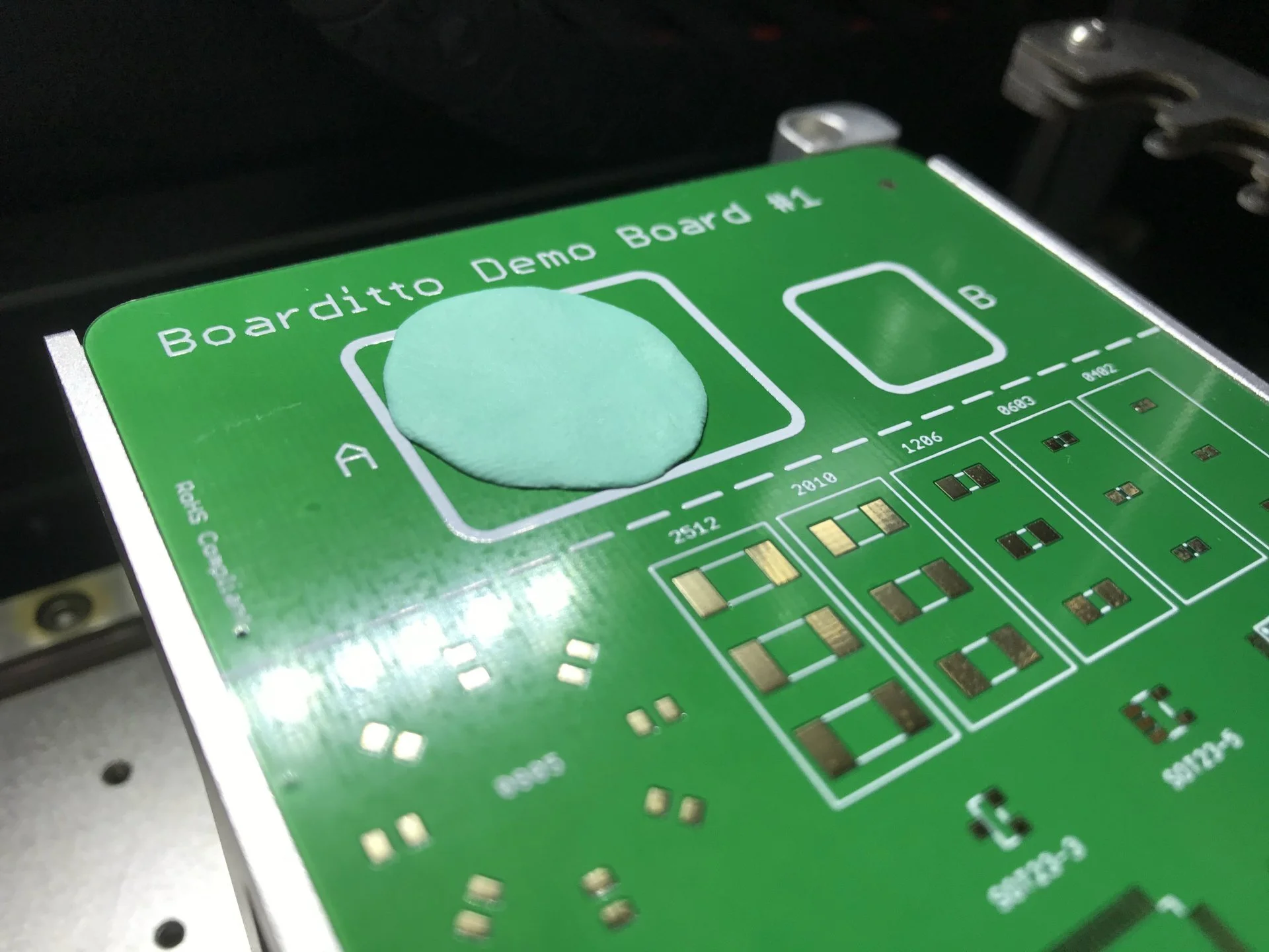
2. Apply the included adhesive tack onto box “A” of “Boarditto Demo Board #1” as shown in the image below. The adhesive tack should be around 2mm thick. Insert this PCB into the PCB holder.

3. Press the button “Go to Tack Area”.
4. Using the crosshairs, find a smooth flat area on the adhesive tack and click “Start“.

5. Look into the machine and slowly drop the nozzle until the tip of the nozzle creates an impression on the adhesive tack.

6. When ready, click “Begin Offset Measurement“.
You should see a circular impression in the top camera view.

7. Move the crosshairs until they are perfectly centered with the impression. When ready, click ”Save Point - Camera High”.

The machine will move the head to another position.
8. Move the crosshairs again until they are perfectly centered with the impression. When ready, click ”Save Point - Camera Low”. Then, click “Save”.


9. Manually remove the nozzle from the head when you’re done.
Calibrate Top Camera Fiducial Offset
1. Insert the PCB “Boarditto Demo Board #1“ onto the PCB holder. Then, click “Go To Reflection Area“.

2. Move the blue crosshairs to the center of the reflected light.

3. Click “Go To Fiducial Area“. This will move the top camera view to the top-right fiducial of the “Boarditto Demo Board #1“.

4. Click “Find Center Red“ until the red crosshairs is centered with the fiducial. You might need to click this button several times to fully center the crosshairs.
5. When ready, click “Save Center Red“.

6. Click “Find Center Blue“ until the red crosshairs is centered with the fiducial. You might need to click this button several times to fully center the crosshairs.
7. When ready, click “Save Center Blue“. Then, click “Save”.

Calibrate Bottom Camera
1. Manually install Nozzle #1 into the nozzle head and click “Move To Bottom Camera“. The button “Spin“ can be used to check for nozzle wobble to ensure the nozzle is properly installed. A very small amount of wobble is acceptable.
2. In the section “Center High”, click “Go To“.
3. Jog until the nozzle tip is centered with the red crosshairs. Then, click “Save“.

4. Repeat steps 2 and 3, but this time with “Center Low“.

5. Click “Go Center“. Make sure it is perfectly centered. If it’s not, repeat steps 2 and 3.

6. In the section “Level the Bottom Camera Image”, click on the “Go Left“ and “Go Right“ buttons alternately and verify that the horizontal line of the red crosshairs cuts through the center of the nozzle tip. If it doesn’t, click on the rotation buttons as necessary to rotate the image until the above conditions are met.


7. In the section “Top Left High”, click “Go To“.
8. Jog until the nozzle tip is centered with the green crosshairs. Then, click “Save”.
9. Repeat steps 5 and 6 with “Top Left Low“, “Bottom Right High“, and “Bottom Right Low“.
10. Click “Save“ when you’re done.


Learn PCB Holder Height
1. Take nozzle #1 and manually insert it into the nozzle head of the machine. Make sure it is inserted all the way in.
2. Move the crosshairs to the position shown in the image below. Then press “Start”.

3. Look into the machine and slowly lower the head until the nozzle tip just touches the PCB holder as shown in the image below.
4. When done, click “OK“. Manually remove the nozzle from the head when you’re done.

Learn Nozzle Holder Height
1. Take nozzle #1 and manually insert it into the nozzle head of the machine. Make sure it is inserted all the way in.
2. Move the crosshairs to the position shown in the image below. Then press “Start”.

3. Look into the machine and slowly lower the head until the nozzle tip just touches the top of the nozzle holder as shown in the image below.
4. When done, click “OK“. Manually remove the nozzle from the head when you’re done.

Set Up Nozzles
1. Insert all four nozzles into the nozzle holder. In “Slot 1”, click on the button “Go To“.

The goal is to move the crosshairs to the center of the nozzle. However, you might notice that the nozzle is slightly tilted while inside the nozzle holder. To solve this:
2. Use your finger and push the nozzle up against nozzle holder so that the nozzle is perfectly flat and level. Then, center the crosshairs with the tiny hole where light is passing through the nozzle tip.
3. Once centered, jog the crosshairs toward the left by 0.2mm. The results should look like the image below. Then click “Save New Position“.

4. Repeat steps 1-3 for the remaining slots (2, 3 and 4). When you’re done with all slots, click “Save”.


Learn PCB Origin Location
1. Move the crosshairs to the position shown in the image below, and click “Save Position“. Then click “OK“.

Learn Recycling Bin Location
1. Remove the recycling bin and move the crosshairs to the position shown in the image below, and click “Save Position“. Then click “OK“.

Set Up Lights
This controls the default brightness of the bottom camera’s red lights. The values are factory set, so there is no need to change them.
