
Import
Last updated: May 8, 2020
This feature lets you import component placement data directly from a pick and place file, which you can easily export from your favorite PCB design program. This feature is useful if your board design has many components. If your PCB’s part count is not high, you can skip this page and follow the instructions from “Set Up Place“.
1. Follow the instructions provided by your PCB design software company for exporting the pick and place file for your board and have your file ready in a USB drive. Plug your USB drive into the back of the machine.
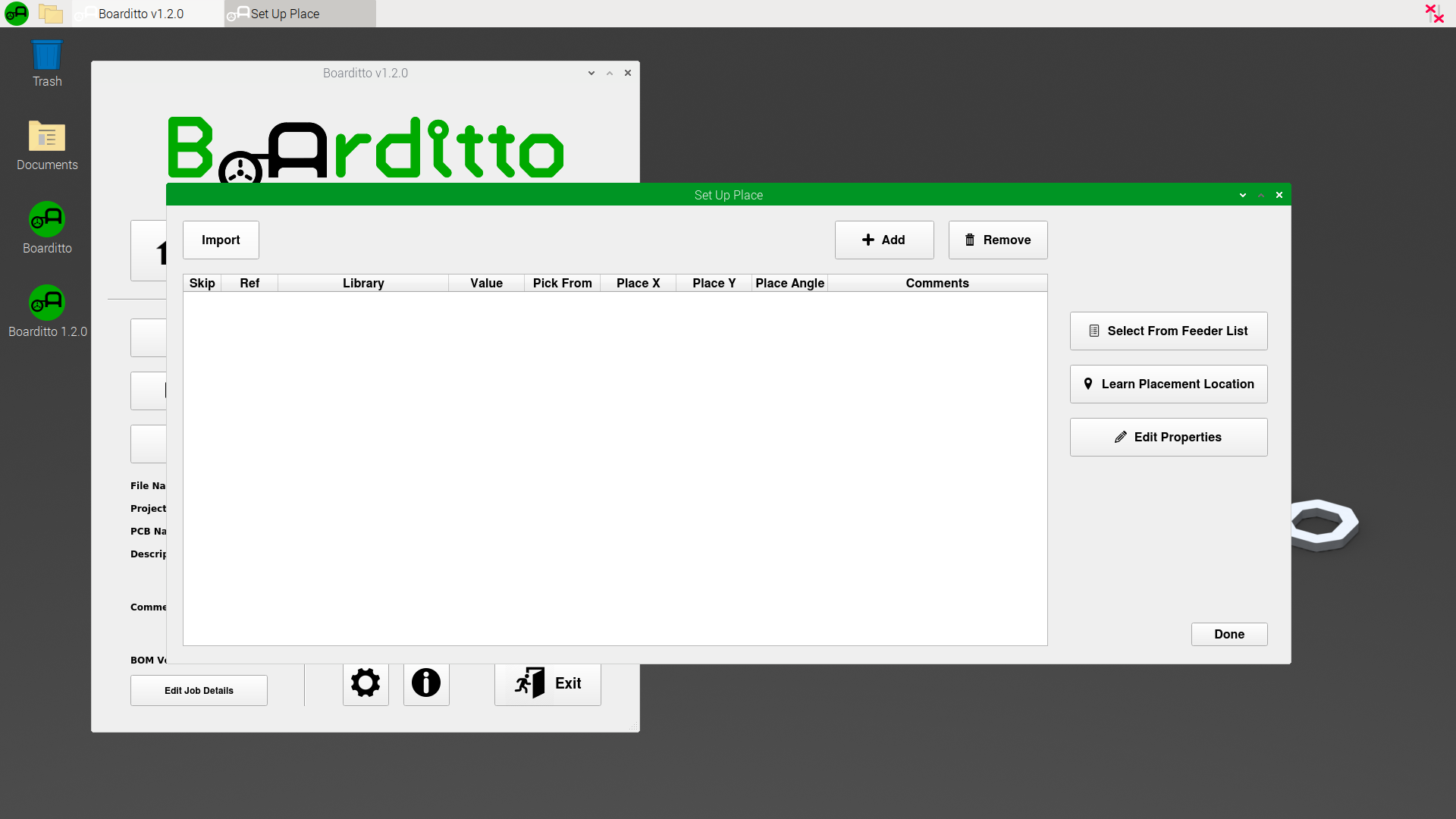
2. Go to the “Set Up Page“ window and click on the button “Import“.
3. Now, click on the button “Import File“.
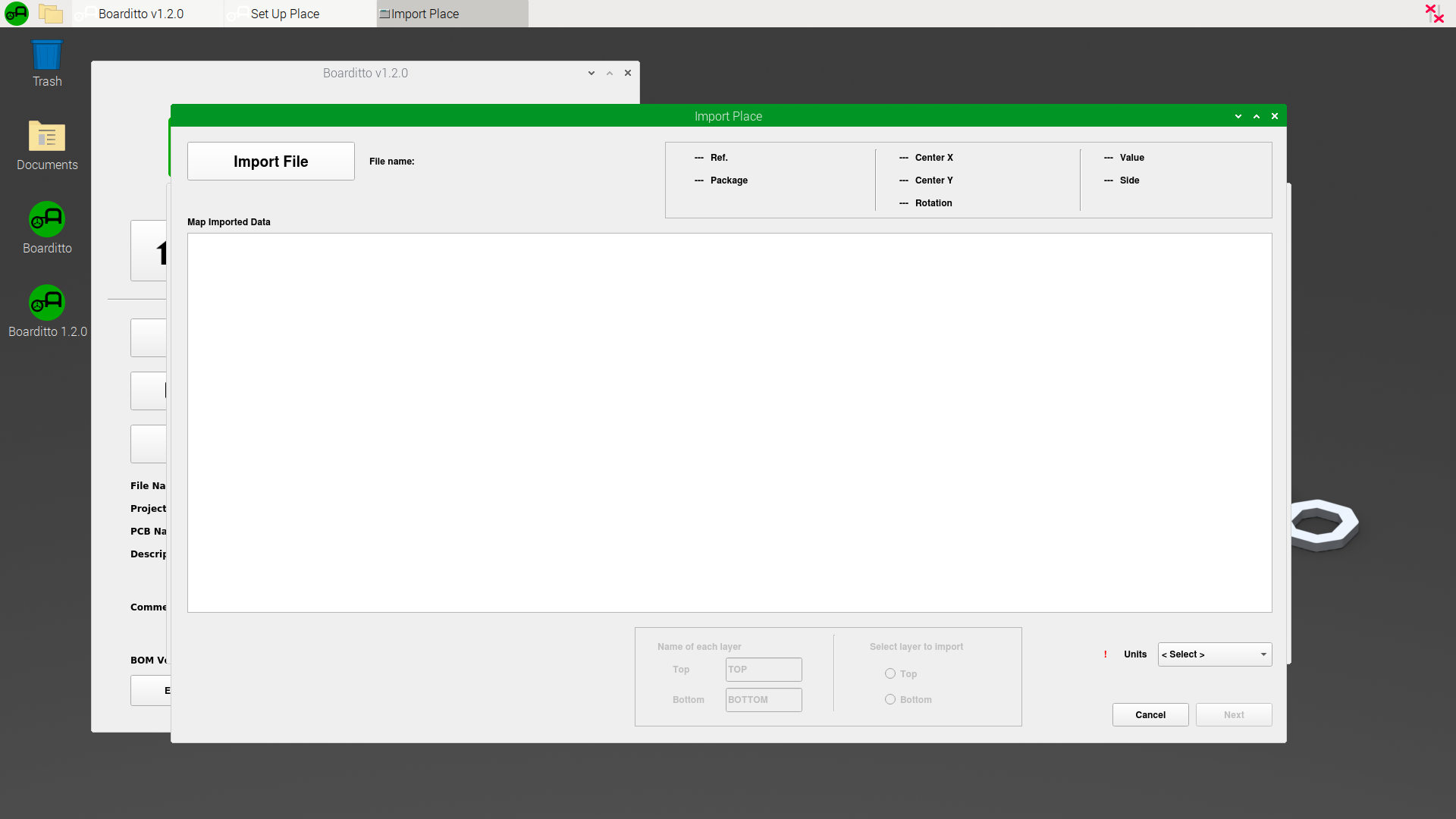
4. Find your file and open it.
5. The imported data should appear in a table. Notice that now there are drop-down lists at the top of each column with the text “<Select>“. The goal is to let the software know what the data columns represent by mapping the columns to the corresponding field (Ref., Center X, Center Y, Rotation, Value, Package, Side).
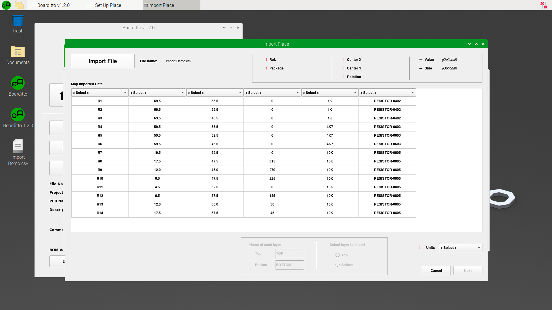
6. The status box at the top right of the window will indicate if there are any problems with your selection.
7. Let the software know what units the file is using via the drop-down list at the bottom right of the window (millimeters, microns, inches, mils).

8. When everything is ready, click “Next“.

You will see two tables in this window. The upper table is a short summary of all packages and values from the import file. The lower table is the final list of components to import into your pick and place job.
9. Select a row from the upper table and click “Select From Feeder List“.

10. Select the feeder that matches the component you’re trying to import.
Note: In order for a feeder to appear in the list, you have to first add it by following the instructions in “Component Training“ and “Set Up Pick“. You can exit the “Import” window at any time and come back to it later after adding the feeders you need.

11. Repeat step 10 for all other components in the list. If you do not want to import a particular package, you can click on the “Skip“ checkbox. You do not need to assign a feeder to a row that is being skipped.
12. Once everything is ready, click “Next“.

The left side of the window shows the general orientation of the components you are placing on the board.
13. You rotate the components by increments of 90 degrees by clicking the “Rotate 90“ button until you get the desired orientation. The components should be oriented according to the way you plan on mounting your PCB inside the machine.
Notice how there are two red circles labeled A and B. The software automatically chooses two components that are diagonally farthest away from each other to use as reference points. The goal now is to let the software know where these two components are located so that it can determine the location of the rest of the components in the import list.
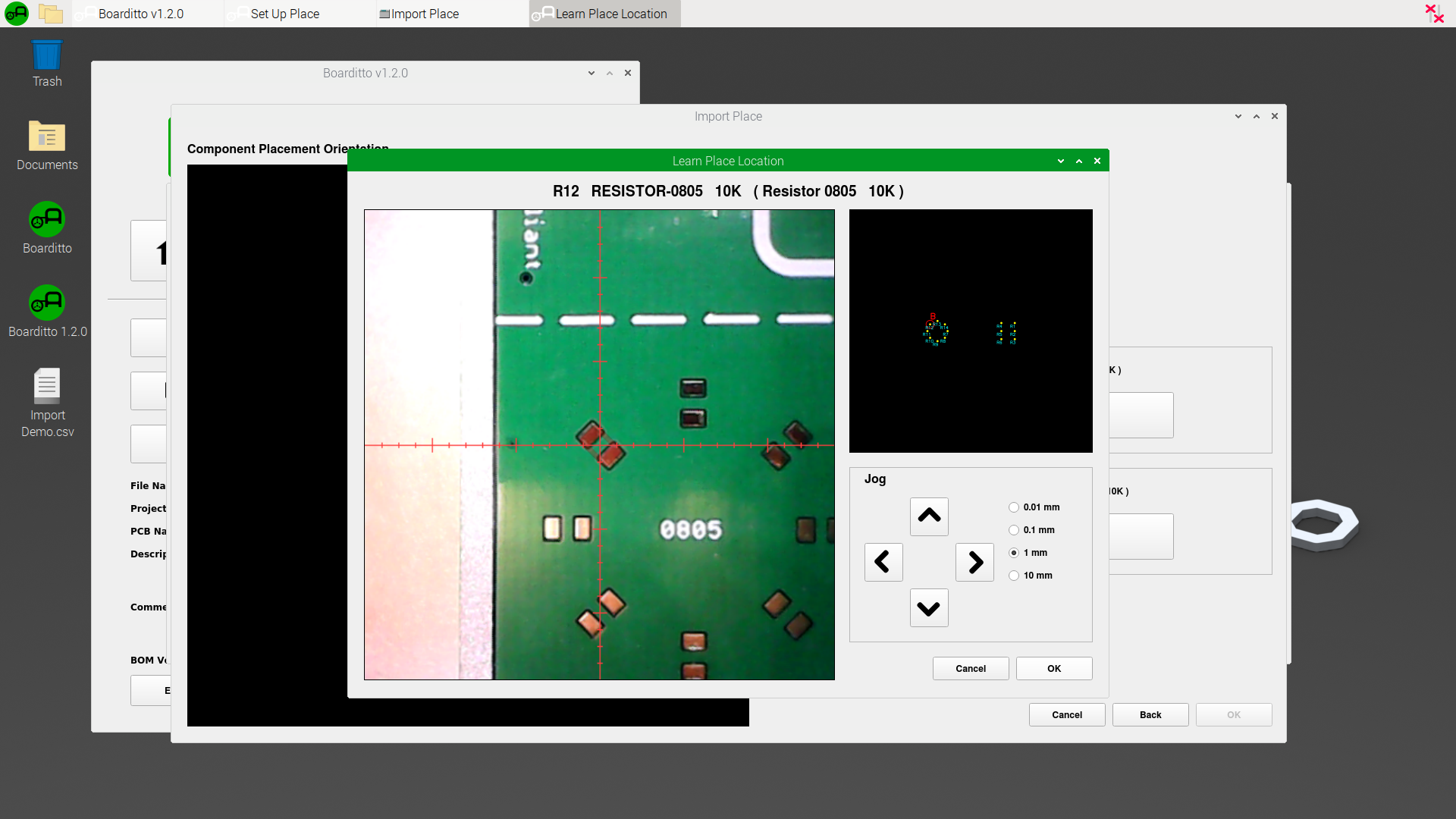
14. Click on the button “Component A - Learn Placement Location“.

15. Find the position of component A and click “OK“ when ready.

16. Click on the button “Component B - Learn Placement Location“.

17. Find the position of component B and click “OK“ when ready.
18. Click “OK“ to complete the import and exit this window.

That’s it! You should now see a list of imported components in the “Set Up Place“ window.

19. To check the results, select a random row and click “Learn Placement Location“.

The machine should now automatically move to the position corresponding the component you’re checking.

Next: Start Production