
Component Training
*** This page is frequently updated. ***
Components need to be “trained” before they can be used in a pick and place job. Training allows the machine to know what your part looks like and figure out how to compensate for misalignment during production. The good news is that you only need to train new components once and this information gets stored inside the machine’s “Components Library” for reuse in future projects.
Let’s train a new component.
Click on the button “Set Up Components”.

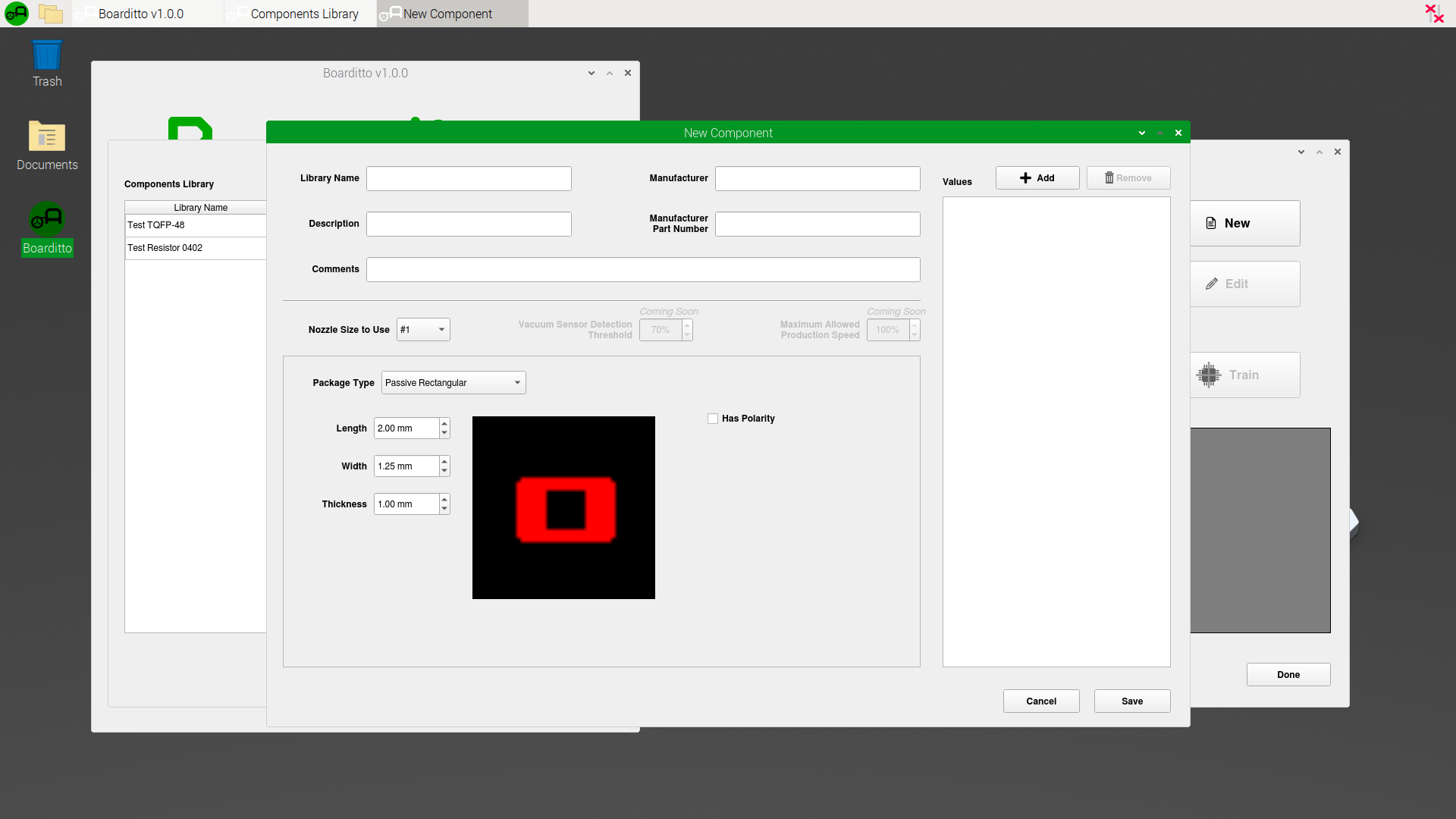
2. To train a new component, click on “New”.

Here, you can input basic information about the part, its dimensions and production parameters.
Selecting the right nozzle size depends mostly on the size of the component. The bigger the component, the bigger the nozzle you should use. There should also be a good air seal between the nozzle tip and the component’s top flat surface.
WARNING! Be careful not to select a nozzle with an inner diameter bigger than the size of your component. For example, if you use the biggest nozzle available to attempt to pick up a tiny 0402 resistor, the nozzle might end up accidentally sucking the component right into the machine’s air tube and vacuum pump system.
The “Values” field is useful when you have the same type of component package for different values. For example, you can have a shared “Resistor 0603” library for the values 220ohm, 1k, 10k, etc. If you don’t need the “Values” field, you can leave it empty.
3. Fill out the required information and click “Save”. It’s always a good idea to refer to the component’s datasheet for the exact dimensions.

4. Notice that there is now a new component in the list. Select the newly created item and click “Train”.

5. Make sure the component you want to train has been loaded into the machine via an automatic, manual or tray feeder. When the component is ready, click on the button “Find and Pick Up Component“.

A new window will appear, showing the top camera’s view.

6. Click on the jog arrows until the crosshairs are centered with the component you want to pick up. Make sure the angle of the component matches the angle shown in the red colored diagram of the component (check pin 1). Select the appropriate nozzle size from the drop-down list. Click “Next“.
Tip: you can also use the arrow keys on your keyboard to jog. Select the jogging distance at the right of the arrow keys.

7. Look inside the machine and carefully lower the height of the nozzle until the nozzle tip exactly touches the top surface of the component. Click “Pick Up Component“.

8. The machine will turn on its vacuum pump to pick up the component and move it into the bottom camera’s view. Click “Done“.

The goal now is to create a perfectly centered and aligned image for the machine to use as reference during production.

9. Click on the arrows to move the crosshairs until it is in the center of the component. Adjust the angle by rotating the nozzle as needed until the image is perfectly level. Use the sliders to adjust the size of the bounding box so that it wraps the component while leaving a small margin around it. It should look like the image below.

10. Once you’re satisfied with the image in the viewport titled “Processed Image“, click ”Save Image” to save the results into the library.

11. Click “Return Component“ and then “Done“.

Next: Set Up PCB