
Set Up Place
Last updated: 10 Jul 2026
Interactive Mode
Import Mode (Optional)
Coming Soon
Initial Preparations
Navigate to the “Set Up Place” tab.
It is recommended to keep the machine lid closed during component placement setup to maintain consistent lighting conditions.
Click “Scan PCB Fiducials”. The machine will quickly locate the previously trained fiducials to verify the PCB’s current alignment. Pressed this button each time you move the PCB or remount it onto the PCB holder.
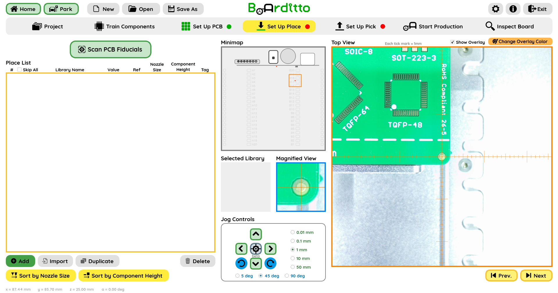
Add Component
Click “Add” for a new entry to appear in the Place List.
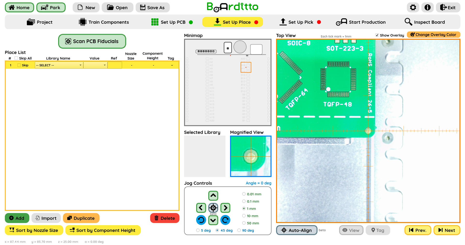
Select the component you want to place from the “Library Name” drop-down list.
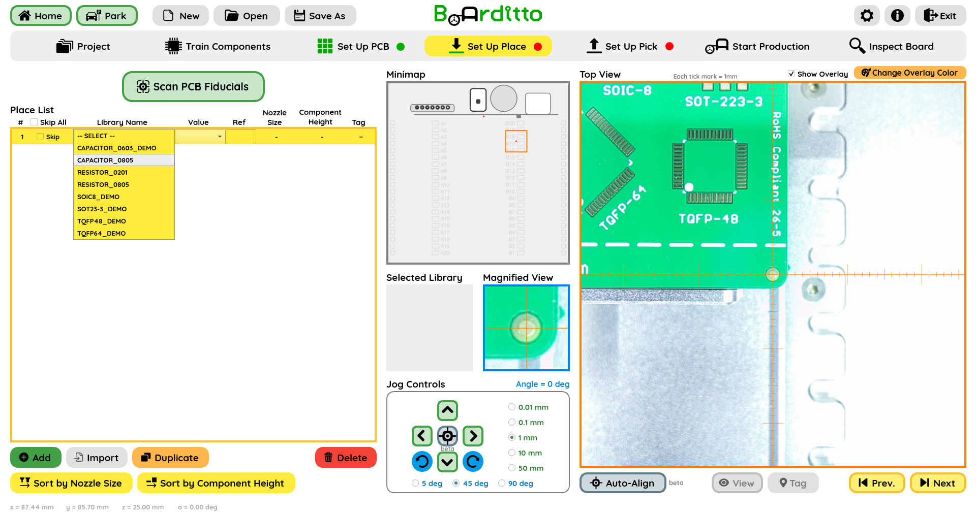
Select the component value (if applicable) from the “Value” drop-down list.
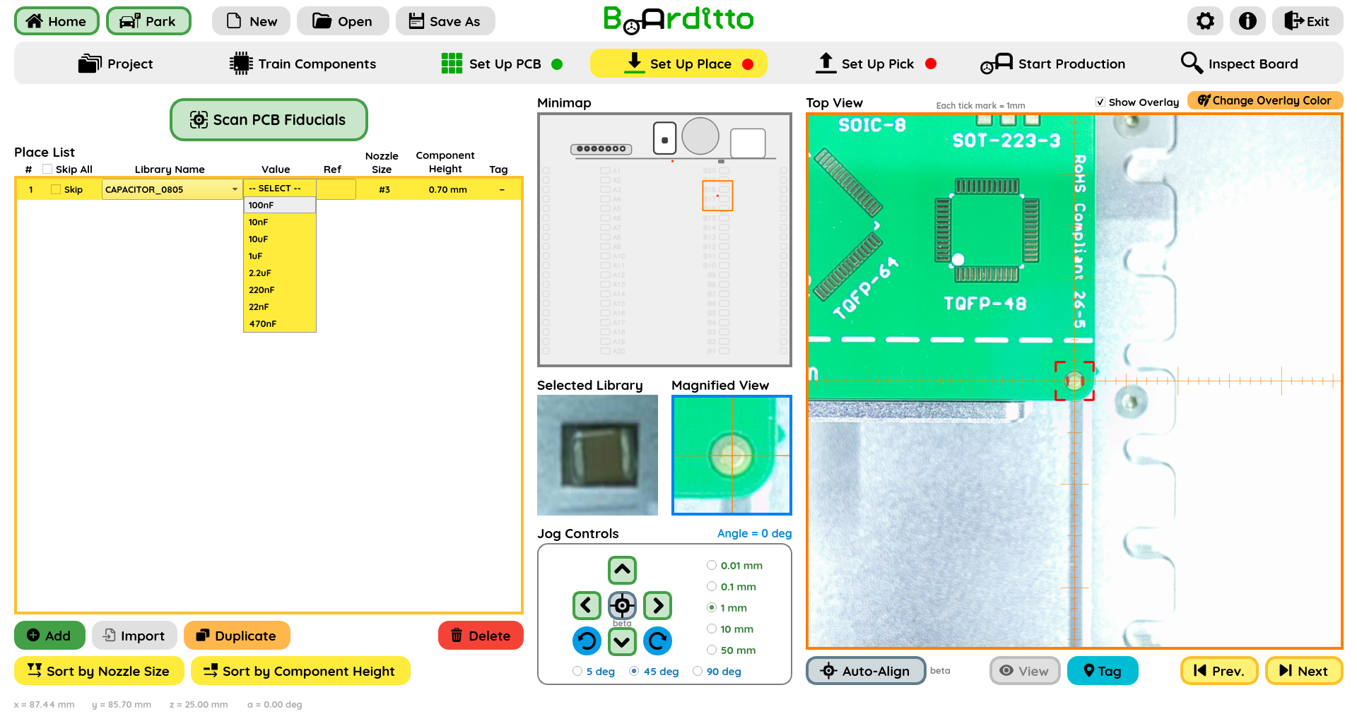
Input the Reference Designator for your component (for example, R1, C2, U1, etc.) or leave it blank.
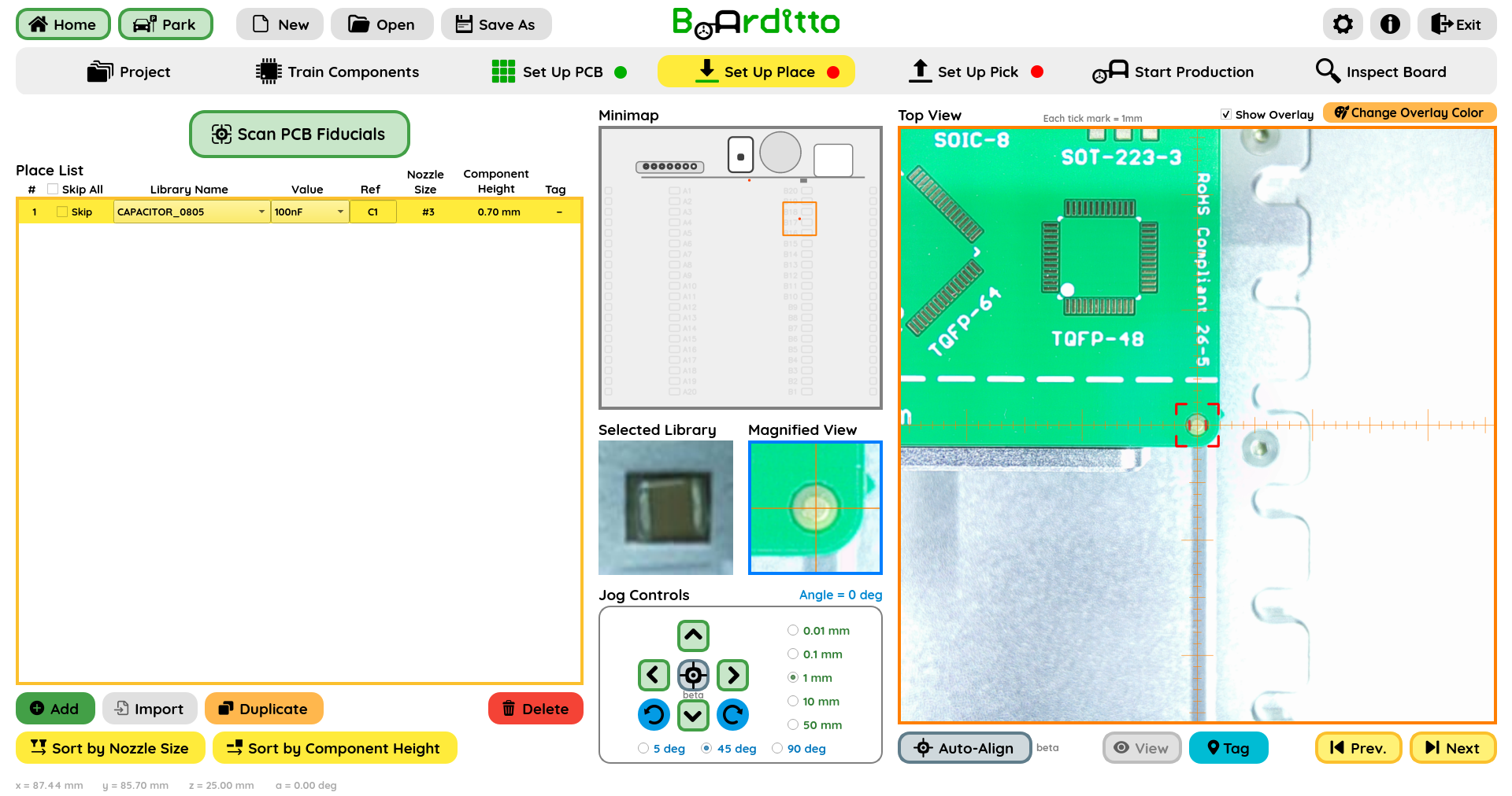
Component Placement Location
Approximately jog to the location where the component is supposed to be placed.
Tip: The “Change Overlay Color” button allows a user to select a color that prevents the overlay from blending with the background, ensuring that both the overlay and the underlying PCB pads remain distinctly visible.
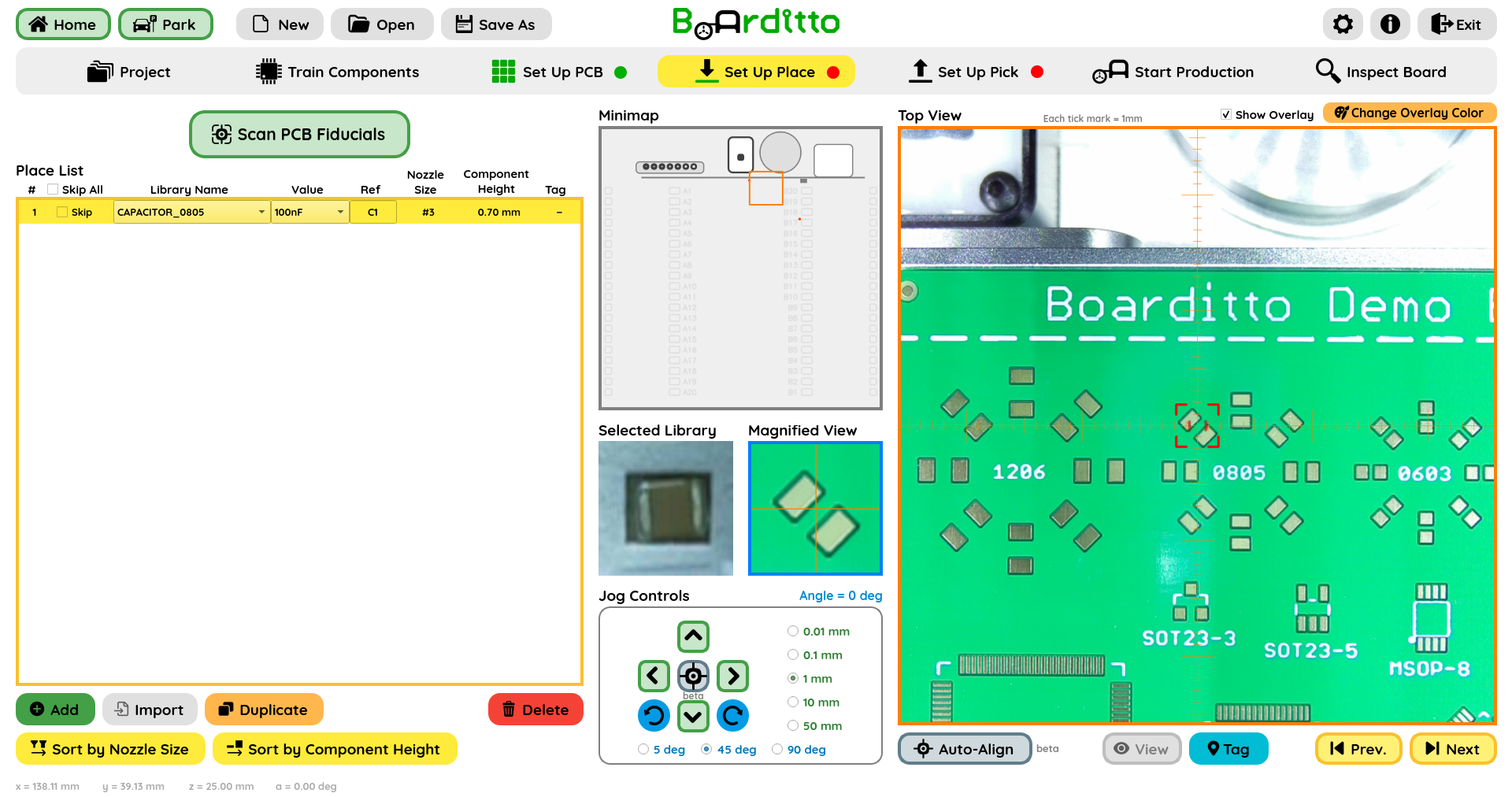
Click on the “Auto-Align” button to automatically center and align the component overlay with the corresponding pads.
Tip: if necessary, you may manually fine-tune the alignment with the Jog Controls or keyboard arrows.
Click “Tag” to save the component placement location.
Additional Place List Controls
Tick the “Skip” checkbox next to a component in the Place List to omit it from placement during production. You can also use “Skip All” and then re‑enable the specific items you want to place.
(Optional) To streamline the production job, select “Sort by Nozzle Size” or “Sort by Component Height.” This minimizes the number of tool changes required and shortens the total production time.
Note for Multi-Board Panels
When using multi‑board panels, train only the top‑right board. The components trained for “Board 1‑1” will be automatically applied to every other board during production.
Next: Set Up Pick